技术
APPLICATION OF THE THEORY OF PATTERN RECOGNITION
IN DEVELOPING RELAY PROTECTION AND CONTROL
V. E. GLazyrin
Reliable and timely recognition of emergency states in electrical systems requires solutions that are adequate for the technical equipment being used. For more than ten years discrete computing devices have been widely implemented in relay protection and control. The appearance of microprocessors has given developers extremely powerful tools for using new principles and algorithms in designing relay systems. Despite this, the design strategy remains practically unchanged, though the new element base exceeds the capabilities of the conventional one to the degree that it is simply on a qualitatively higher level. In connection with this, the necessity has ripened for qualitatively new approaches to designing relay systems.
Conventional design methods very much depend on the intuition and experience of the developer. The execution of the work is frequently unpredictable, since the developer must simultaneously represent the state of many (sometimes more than ten) parameters. At the same time, a person has a limited capacity to simultaneously keep in mind many objects. This causes not only complexity in developing new devices, but also causes the subjective phenomenon of a group of relay protection experts which have on an intuitive level mastered a combination a several groups of concepts. This reduces the number of objects which must be kept in mind simultaneously, but the formation of these combined groups has not been formalized, which hinders mutual understanding.
During the development of new complex devices of relay systems, the quantity of parameters, with which the developer has to work simultaneously increases even more. This not only complicates the design, but also increases the probability of errors, which simultaneously hinders the control of the accuracy of the execution of activities for creating algorithms, designing devices, writing programs and conducting correction tests. In the conventional design approach, a successive analysis of signals is made and decisions are made as they are received. In so doing the evaluation of the current state of the examined object is carried out by the successive analysis of transitions of measuring from one condition to another. This approach to developing algorithms has also become a constraining factor in developing effective algorithms.
As an example, we shall consider one of the complex relay system devices, detectors of asynchronous operation. The most developed are those detectors having remote units and units for direction of power. An asynchronous mode is recognized by analyzing the sequence of transitions of the measured resistance value which is defined by the relationship with the voltage and current inputted into the measuring units. During the operation of the object, the end of the vector Z, can move relative to the operating ranges of the units depending on the character of the operational mode.
The standard device consists of three relay assembly of resistance, having various characteristics of switching, of maximum relay assembly of power and of counter of cycles of asynchronous operation. In addition, it contains a unit for determining the sign of the slip, circuits for registering the asynchronous mode in the first cycle, circuits for controlling the period of asynchronous operation, a unit for additional time. grading, unit for resetting the device, and also circuits for registering a fault in the device, the signaling system , and the output circuits. The device consists of three stages, each of which has output circuit .The first stage is intended for the fastest detection (in the first cycle) of an asynchronous mode in the controlled section and the sign of the slip. The second stage is intended for the detection of an asynchronous mode in the controlled section and the sign of the slip at the end of the second, third or fourth cycles. The third stage is intended for liquidation of the asynchronous mode after executing measures for resynchronization, if during the additional time lag a specific quantity of cycles of the asynchronous mode are registered. Besides that, in order to make sure the device does not operate during short-circuits a unit of reverse sequence for blocking the device in asymmetrical modes is advisable.
Thus, it is clear, that the device contains a great number of units working jointly. It should also work in various ways depending not only on the combination of the states of its units, but also on the relationship between the times that input units are found in various states. That means that the behavior of the device should depend on a combination of the states of a large number of operational units, and the time relationships of appearance and disappearance of signals from various units also must be taken into consideration. The description of the logic of the operation of such a device constructed using a conventional element base is adduced in and takes more than 20 pages. The device itself is made in the form of a standard relay panel. Attempts to make a formal description of the logic of the device's operation, which would be convenient to use to create an effective program for a microprocessor, have turned out to be very labor-consuming and have not given a reliable outcome.
To overcome this difficulty a special mathematical apparatus has been applied that has received the title "theory of a pattern recognition". It has broad application in other areas of science and engineering, such as radio-location, echo-location, processing the outcomes of air photography for agricultural needs, and also for technical diagnostics. Applying the method of pattern recognition assumes parallel information processing. The prototype for such processing is human perception, which takes the entire input data and practically instantly comes to the most valid solution which determines its response to changes in its external environment.
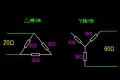
For the design of a microprocessor detector of asynchronous modes the following characteristics of operation of measuring devices were adopted. For remote devices the characteristics of operation are adopted as anti-parallel programs, whose bases coincide and lateral legs are located in such a manner that the sensitive device envelops a larger area, than the rough one, and middle lines coincide. The power direction unit has the characteristic of a straight line running along the middle line and its extensions. The position of operational zones of remote devices in a complex plane of resistance is selected so that they envelop a financial calculation center of hunting.
In such an arrangement of operational characteristics, the entire complex plane of resistance is broken into 6 zones. If the resistance Z, falls into the operating range of any unit, then it corresponds to a "1" in the appropriate position of the unit state register. Otherwise "0" is installed in this position. Thus, for the full description of the state Z, relative to the operating ranges it is enough to have three positions, which are combined into "a code of the state of measuring devices" (CSMD). Since for the detection of an asynchronous mode it is not important in what zone is Z, at the given moment but in what order and with what speed it passes these zones, a 16-digit word is formed, in which current CSMD values are recorded in turn at the moment of transition of Z, from one zone to another (before recording CSMD in rightmost positions of the word there is a logical shift to the left by three positions). Thus, the information on the trajectory of motion of the end of vector Z, during the period it passes by four boundaries between zones is stored in one 16-digit word.
Possible paths of motion of the end of vector Z, during asynchronous mode correspond to a rather limited dictionary of indicators, which allows, not only an asynchronous mode to be discovered but also allows the determination of the direction of relative motion of EMF, vectors in an asynchronous mode.
Research of the behavior of the microprocessor detector, using' this method of analysis of the system state, has shown that detection of an asynchronous mode in the first cycle is impossible without taking into account the duration of time of the presence of the end of vector Z, in each zone. Therefore, for a more full characteristic of a transient image, a check of the duration of the presence of the end of vector Z in each zone is entered in the algorithm. If its duration in an appropriate zone turns out to be more than a given threshold, then the fact of its exceeding the limit is recorded in an additional register "code of a timer conditions" (CTC). Similarly to CSMD, values formed in CTC at the moment of transition from one zone to another, are recorded in a word of time states (whose formation is implemented by a logical shift of the previous value and an adding of the new value).
The introduction of additional information has permitted expansion of the dictionary, by including in it combinations which take into account not only trajectory of motion, but also the duration of the end of vector Z,in each zone. To realize an operational algorithm of the asynchronous mode detector it is enough to register an excess of duration of the end of vector Z, in the given zone above the threshold value.
The use of time thresholds allows to reliably determine, whether the preceding mode was a long normal mode of joint activity of power systems. Because of this, the "first stage" of an asynchronous mode detector is realized, since the first cycle of an asynchronous mode will always come after a long working mode. For detection of a long working mode it is enough to make sure that over a large enough time span the end of vector Z has been outside of the operating ranges of remote devices.
The control of the duration of the end of vector Z in one of the zones is also necessary for detection of a distinctive feature of an asynchronous mode which is exhibited most clearly in the first cycle, substantial difference in the time between the entrance of the end of vector Z, in the operating range of the sensitive remote device and its entrance into the operating range of the rough one.
The use of this indicator allows to reliably distinguish a short-circuit mode, in which the transition from the normal mode zone into the operating range of the rough remote device happens practically instantly.
One more important factor that limits the efficiency of using conventional asynchronous mode detectors is the large switching time of analog measuring devices near a operational zone boundary. This is the reason for failures in operation when the slip is large. The application of digital algorithms in the construction of remote devices and power direction device enables this shortcoming to be overcome.
In selecting device parameter settings for liquidation of an asynchronous mode a big difficulty is selecting operating zones of measuring devices because the selected thresholds should satisfy the whole set of operational modes of the considered section. Frequently selecting thresholds for one set of measuring devices turns out to be difficult. Using several detectors to detect an asynchronous mode in one section is not usually considered because of the cost of this solution. But, implementing microprocessors using the theory of pattern recognition can provide the necessary quantity of detectors, which have various zones of measuring device operation, without additional hardware costs. Hence, enough detectors can be realized in the microprocessor system, that the necessary properties can be achieved.
It should be noted that the approach to detecting abnormal and emergency operation in relay systems using the theory of pattern recognition is not limited only to asynchronous mode detectors. It would be expedient to investigate the possibility of using this approach in the synthesis of algorithms and other kinds of complex devices of relay systems.
继电保护发展和控制中图样识别理论的应用
V.E. GLazyrin
俄罗斯新西伯利亚州工业大学
电力系统紧急情况状态的可靠和实时性识别要求对使用的技术设备做出恰当的反应。 十多年以来,分立的计算测定装置在保护并且控制得到了广泛的实现。微处理器的出现给了开发商极强有力的工具来运用新的原则和算法设计保护系统。 尽管如此, 设计策略实际上并未改变, 可是新的元件基地在一定程度上超出了常规元件的能力,这种程度简单地是一定性地高水平。与此相关,用新方法定性地设计保护系统的必要成熟了起来。
常规设计方法非常取决于开发商的直觉和经验。工作的施行频繁地变化莫测, 因为开发商必须同时描绘许多(有时超过十种)参量状态。同时,人同时记住许多东西的能力是有限的。这不仅造成了研发新设备的复杂性,而且导致了一组保护专家的主观现象,这些专家在直觉的水平上掌握几个小组概念的组合。这减少了能同时记住的东西的数量,但这些联合小组的形成还未形式化,这就阻碍了相互的理解。
在保护系统新的复杂装置的研发期间,开发商运作时更增加了同时需要的参数的数量。 这不仅使设计复杂化,而且增加了出错的概率, 这同时也阻碍了对创造算法,设计设备,编写程序,校验更正的准确性的控制。在常规设计方法,随着信号的被接受,进行着对信号的连续分析,同时做出决定。这样做,要通过对由一种情况到另一种情况所测得的变化的分析,进行被检测对象的现状的评估。开发算法的这种方法成了开发有效算法的一个强迫因素。
例如,要考虑设计一个复杂保护系统装置,异步操作探测器。 最先进的是具有远程元件和功率方向元件的那些探测器。 异步方式是通过分析阻抗测量值的变化结果而识别的,阻抗测量值是由测量单元所测得的电压和电流决定的。在对象的操作期间,向量Z的末端可以移动于相对由运行状态特点的单元运行范围 。
标准装置包括三个阻抗保护装配,有开关的各种特征,是功率最大量的保护装配,也是异步运行方式循环的计算机。另外,它还包含一个测定事故信号单元、记录一级循环异步运行方式的回路、控制异步运行时间的回路、附加时间回路、装置改装单元、故障记录单元、信号系统和输出回路。这种装置包由三个阶段构成,每个阶段都有输出回路。第一段用于对控制部分和故障信号中的一级循环异步方式进行最快的监测,第二阶段用于对控制部分和故障信号中的二、三、四级循环末端异步方式进行监测,第三段用于在执行再同步措施之后对异步方式的清算,如果在附加的时间间隔期间记录异步方式周期数量。除此之外,为了确保装置在短路时不动作,用于阻碍装置进入不对称方式的相反程序应用其中。
因此,很清楚,这种装置包含有大量联合运作的单元。同时它也运行在各种方式下,这些方式不仅取决于各单元状态的组合,而且还决定于各种状态中发现的输入单元的时间之间的关系。那就意味着装置的行为取决于大量运行单元状态的组合,并且必须考虑各单元信号出现和消失的时间关系。对这样一种应用常规原理基础构造成的装置的运行逻辑的描述,举例论证大概需要20多页。这种装置本身是由标准继电器面板的形式制成的。企图对装置的运行逻辑进行正式描述,结局会是大量消耗了劳动力,而且也可能得不到一个可靠的结果,尽管用它来为微处理器创造一套有效的程序可能会很便利。
为了克服这个困难,一种专门的数学仪器应用其中,那就是“图案识别理论”。它宽广地应用在其他科学领域和工程学,例如电波探测器探测,回音定位,处理为农业需要的空气摄影的结果,也为技术诊断需要。运用图案识别方法就是假设信息处理是并列的,这种处理的模型是人的感知,它获取全部输入数据后立即给出有效的处理,所得出的处理信息决定它对外部环境的反应。
对异步方式微处理器探测器的设计时,以下测量装置动作的特性应被采取。对远程设备,动作特性也被作为反并列程序所采取,它的底线一致;横向支柱位于这样的一种状态,即灵敏的设备较不灵敏的覆盖了大部分面积;中线也一致。功率方向单元有从中线到其延长线这条直线的特征。远程设备操作区域的位置在一个阻抗复平面上选择,以便他们包围的一个预测振荡中心。
在这样一个动作特性的安排中,整个阻抗复平面分成6个区域。如果阻抗Z进入任一单元的动作范围,然后它对应到一个“1”在部件状态记数器中的适当位置。否则“0”在这个位置安装。因此,对于状态Z的完整描述,相对于动作范围它有三个位置就足够了,这些被结合成“测量设备状态的代码” (CSMD)。因为对于异步方式的检测来说,重要的并不是哪个区域是Z,而是在特定时刻它按什么顺序和以什么速度通过这些区域,16位字形成了,用16位字依次记录Z变化时刻的当前CSMD值,从一个区域到另一个(在字的最右位记录CSMD值之前应向左面逻辑移位三个位置)。因此,关于向量Z末端移动轨迹在通过四个区域之间的边界线时,是用一个16位字存储的。
矢量Z末端移动的可能路径,在异步方式对应于一个相当有限的显示词典期间,期间不仅允许能发现异步方式,而且允许异步方式下EMF矢量相对运动方向的确定。将被发现的不仅一个异步方式,而且允许EMF的相对运动的方向的确定。
用这种系统状态的分析方法对微处理器探测器行为的研究,表明第一循环异步方式的监测在不考虑每个区域中矢量Z末端出现时间的持续情况下是不可能的。因此,对于一个瞬变图象的更加充分的特征,对每个区域中矢量Z末端出现的持续期间的核对被输入到算法中。如果它在一个适当区域的持续期间不只是一个阈值,那么超过这个极限值的现象就会被记录在附加的CTC计数器中。类似于CSMD,在从一个区域变化到另一个区域的时刻,CTC值形成了,同时在计数状态下被记录下来。
附加信息的引入允许了字典的扩展,包含于其中的是不仅要考虑运动轨迹,而且还要考虑每个区域中矢量Z末端的持续期间。为了实现一种异步方式探测器的操作算法,记录阈值之上特定区域中矢量Z末端持续期间的超额足够了。
时间门限的用途是准许可靠地确定前述的方式是否是动力系统联合活动的一种长期正常振荡型。正因为如此,一台异步方式探测器的第一阶段得到了实现,因为一个异步方式的第一循环总是出现在一个长的运作方式以后。对于一个长的运作的方式的监测,确保矢量Z的末端已经在一个相当长的时间间隔内超出了远程装置的运行范围。
一个区域中矢量Z末端持续期间的控制对于监测异步方式的显著特征是有必要的,这种特征在第一循环中更能展现出来。
使用这显示器能可靠地区别短路方式,在这显示器中,从正常振荡型区域到粗略的远程设备的动作范围的变化会立即出现其中。
限制使用常规异步方式探测器效率的一个重要因素是测量动作区域边界附近设备的相似体的最大开关时间,这就是大事故时动作失败的原因。数字式算法在远程设备和功率方向设备构成中的应用克服了这个缺点。
在选择装置参量定值清算异步状态时,选择测量装置的动作区域是个难题,因为选择动作值应满足被考虑部分的运行方式的整个设置。频繁地选择一套测量装置的门限是很困难的。由于这种方案的费用问题,用若干个探测器探测一个部分的异步方式通常不被采用。但是,使用图案识别的理论实施微处理器可能提供探测器的必要数量,其中含有测量设备各种各样的动作区域,没有另外的硬件费用。因此,在微处理器系统中可以识别足够的探测器,也可以实现必要的属性。
值得注意的是,用图样识别理论监测继电保护系统中的不正常运行状态和紧急状况的方法没有被限制到异步方式探测器。 这对调查在算法的综合和其他复杂继电系统装置中运用这种方法的可能性是有利的。